Hi
Can anybody give me some advice on installing a new motor onto my compressor?
Basically I've bought an huge old belt driven compressor, the only thing missing was the motor. So Ive bought a new 240v(single phase) 3hp clarke induction motor.
I've wired new cables into the pressure switch and then back out to the motor...this is where I'm stuck . Here's the board on top of the motor...

The six wired brass bolts were pre wired that way from the shop and so all are correct and present, the only wires that need connecting are the three in the top corner from the pressure switch, blue, brown, copper.
To add to the confusion there is a reset switch on the bottom of the casing which is connected on only one terminal, so I'm guessing something needs to be wired to that aswell.

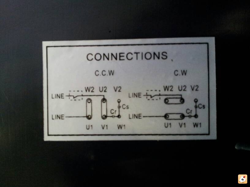
There are no instructions with the motor, only this diagram on the casing

I'm stumped :screwy: There's a lot of clever people on here so can anyone help?
Can anybody give me some advice on installing a new motor onto my compressor?
Basically I've bought an huge old belt driven compressor, the only thing missing was the motor. So Ive bought a new 240v(single phase) 3hp clarke induction motor.
I've wired new cables into the pressure switch and then back out to the motor...this is where I'm stuck . Here's the board on top of the motor...

The six wired brass bolts were pre wired that way from the shop and so all are correct and present, the only wires that need connecting are the three in the top corner from the pressure switch, blue, brown, copper.
To add to the confusion there is a reset switch on the bottom of the casing which is connected on only one terminal, so I'm guessing something needs to be wired to that aswell.

There are no instructions with the motor, only this diagram on the casing

I'm stumped :screwy: There's a lot of clever people on here so can anyone help?
